

Gareth Samuel is a science educator and frequent contributor to the Thunderbolts Project. He also produces an outstanding video series on Electric Universe theories that aims at the very heart of science. He chose the perfect title for his YouTube channel: “See The Pattern”. If a repeating pattern emerges from Nature, we should recognize it as significant. To truly understand it, we should be able to explain it’s cause and effect and reproduce it. Seeing the pattern and discovering it’s cause and effect is what science is. The “proof” is in recreating the pattern. Not by subjectively programmed and data-fixed mathematical models, but by physical demonstration of the physics involved.
This essay presents a challenge for those with a knack for playing with electricity. I’ll show you a pattern. I call it the “Keystone pattern” because it is a pattern of “key” significance. It’s effect can be found in geology, so it’s written in “stone”. It is a pattern that results from electrical discharges. I will show you this pattern and explain it in the best, plain-language detail I can. Then it will be up to you to reproduce it. It shouldn’t be hard.
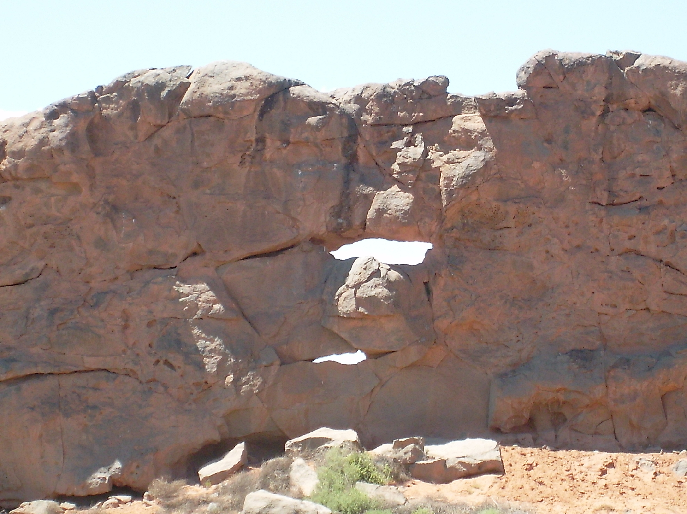
In fact it’s been done before. You may know the pattern as the “crooked smile” if you’ve followed the Electric Universe for several years. Michael Steinbacher and Billy Yelverton produced the pattern in image shown. I believe it was Michael that called it the “Crooked Smile”. I’m giving it the “Keystone” name because the “smile” is only part of the pattern.
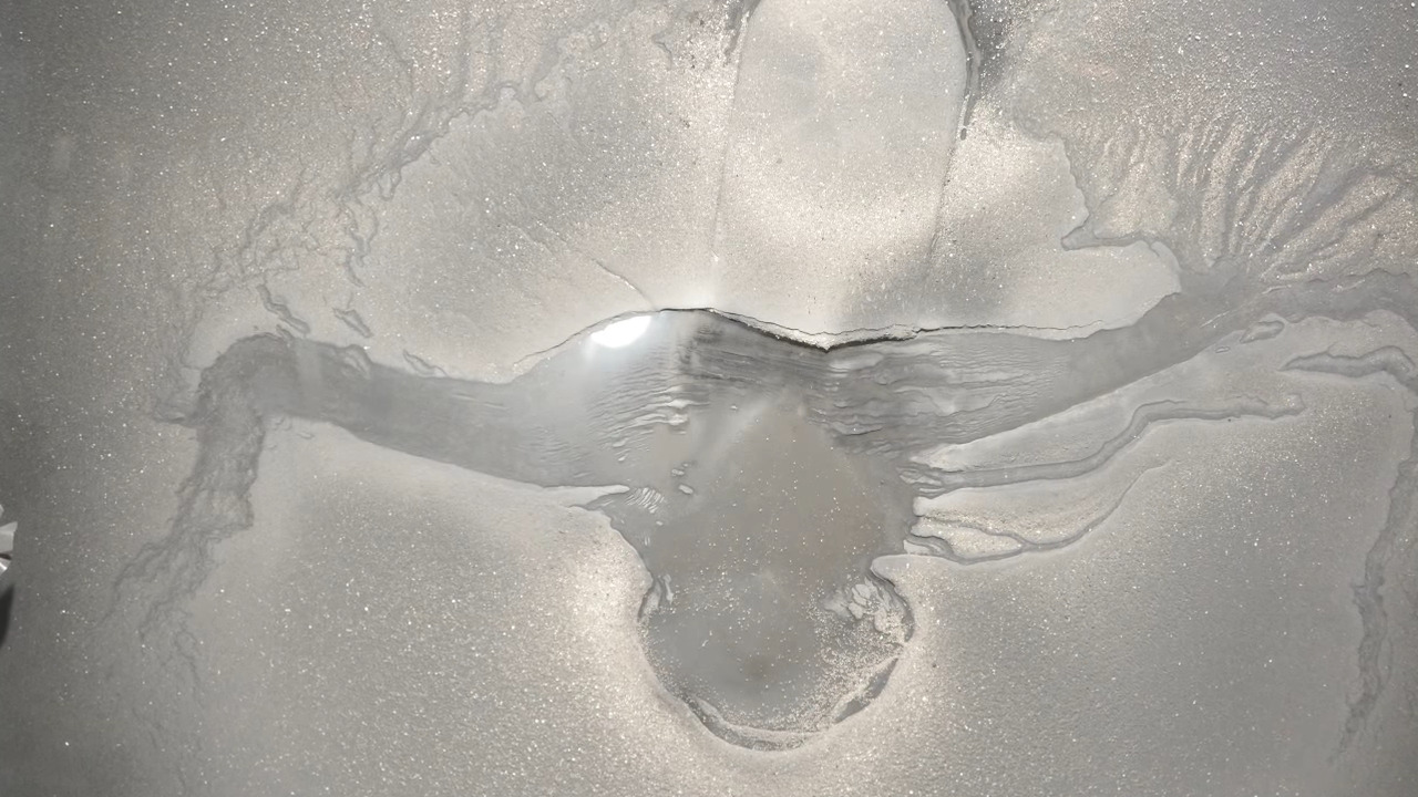
Michael intuitively understood this pattern was the result of a multi-phase discharge. He was trying to reproduce the shape of Valles Marinaris on Mars. He assumed, correctly, that by creating a discharge in Billy’s laboratory with the proper set-up, they could reproduce Valles Marinaris, and they did. Unfortunately, they didn’t explain their experimental set-up, so we’ll have to guess.
My guess is they laid a metal plate on a table, to form one electrode. They covered the metal plate with a dielectric plate, probably glass or plastic, to add resistance and enhance the reactive power. Then they hung another electrode a few inches above the plate and covered the plate in sand.
I believe they then took two leads from a 3-phase power source, stepped them to high voltage and connected one lead to the plate and one lead to the hanging electrode, creating a point-to-plane electric field between two out-of-phase circuits.
The pattern is caused by electrical induction currents that spread out in the horizontal plane from the vertically oriented, multi-phased discharge between the electrodes. These type of induction currents are called “reactive power” currents. You can think of it like aiming a firehose at the floor. The stream of water from the nozzle is an analogy for the vertical discharge current. In terms of electricity, we call that real power, because it’s going where we want it. The water that splashes from the floor are reactive currents, or reactive power currents in the case of electricity., that are splashing across the electrode plate.
The stream of water hitting the floor is like electrical current hitting resistance. Reactive power is the energy of currents that get re-directed by resistance. The “splash pattern” that reactive power makes is peculiar, and very specific to electro-magnetism. Unlike water that splashes away vectored by kinetic energy and gravity, an electric current generates moving electric and magnetic fields that vector its reactive energy. So, it generates a repeating fractal pattern. Reproducing it in the lab is as compelling as scientific evidence can get.
It’s also compelling when you can find it in Nature over and over again. We are going to use it to identify several electrical craters here on Earth, and doing so dispel the silly notion that Earth has been bombarded by asteroids and comets. Here is the Keystone pattern:
The pattern occurs over the duration of the discharge, while it is in contact with the ground and making a complete circuit. Over time, the voltage vector of reactive power shooting out from the focal point, rotates around the pattern like the second hand of a clock, pointing to all points on the compass, only it sweeps around counter-clockwise instead of clock-wise. The current that follows this voltage vector lags behind it, like the minute hand of the clock chasing the second hand, but never catching up.
At the same time magnetic fields are pulsing outward in concentric waves from the focal point and inducing current to follow it. This sets-up an interference pattern of positive and negatively charged regions around the circle formed by the induced currents, where the sand grains which also carry charge are either attracted or repelled. It is much like a cymatic pattern created by a particular frequency of vibration, only this is caused by induced, out-of-phase currents. Where the charge on the plate is the same as the sand, the sand is levitated away, which is technically called sputtering, to region of opposite charge where it sticks to form a mountain.
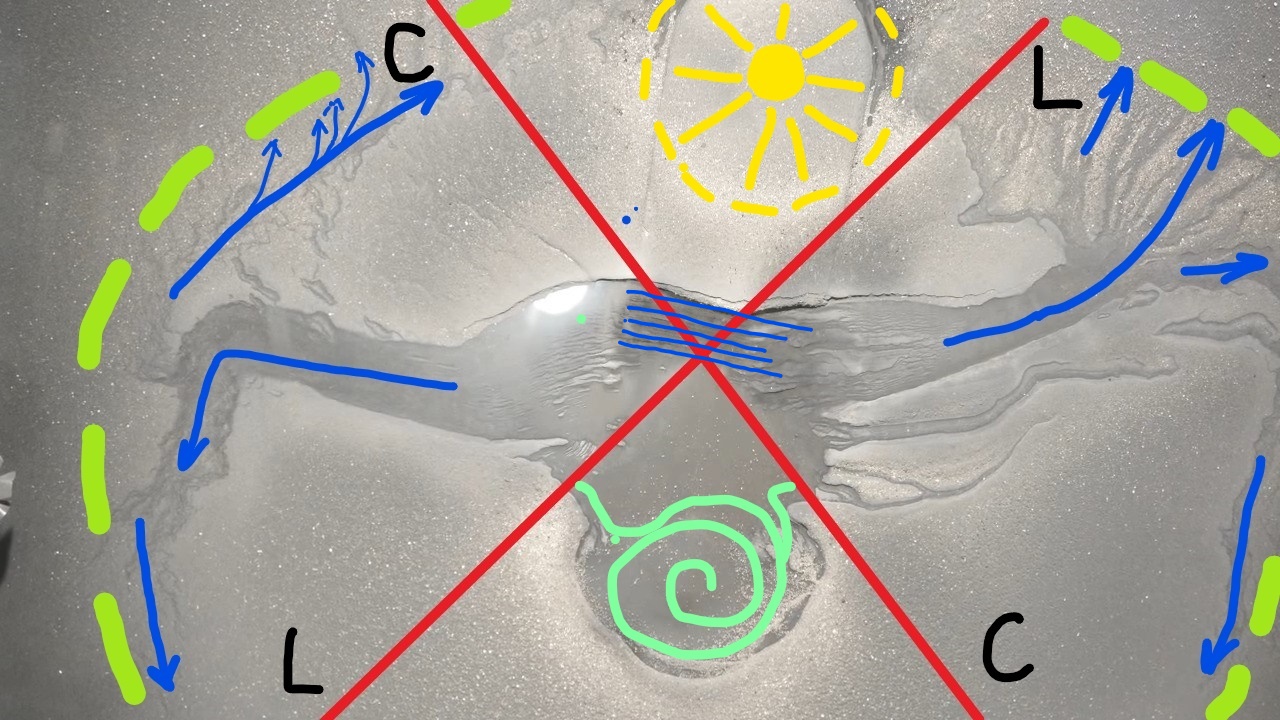
The Red Cross – represents primary reactive currents that “splash” at particular vectors from the discharge focused at the center of the X. C is a filament of electric induction, or capacitive reactive current. L is a filament of magnetic induction reactive current.
The Green dashed circle – represents “stray capacitance” generated in concentric rings around the focus of the discharge by magnetic fields. These are rings of step-potentials expressed as hills and valleys, mountains, or crater rims in geologic formations.
The Blue Lines are the “crooked smile” and portray induction currents following the electric, or magnetic fields, or both.
On the left hand quadrant formed by the Red X, electric field induction dominates and the current flows straight to the encircling ring and makes a 90 degree turn to follow parallel to the ring, because the capacitor ring is a standing potential wave in the electric field.
The quadrant on the right is the magnetic induction dominated region, so current streams out perpendicular to magnetic field lines, induced by the magnetic field. These lines intersect the green rings at 90 degrees.
In the center, through the top quadrant are Bars of Blue. The bars are unipolar winds that drag straight across the focal point of the discharge. They are probably the easiest to identify feature of reactive power currents.
The “crooked smile” is a fractal circuit pattern of capacitive and inductive eddy currents in these particular quadrants of reactive power. The direction of current flow can go either way, depending on polarities, so I don’t usually show arrows in diagrams.
The top and bottom quadrants are where reactive currents form updrafts and downdrafts. The Yellow Star in the top quadrant is a downdraft current, and the Pale Green Swirl in the bottom quadrant is an updraft. These would be tornadoes and downbursts of plasma wind and lightning. They generally leave circular patterns of depressions, or hills. The next image shows the same features more fully annotated.

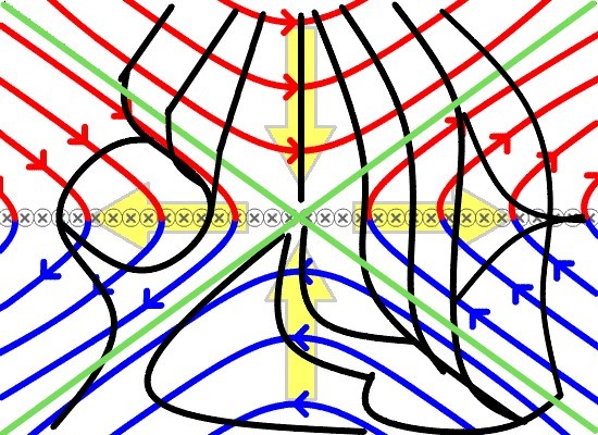
Note how the right-side magnetic induction currents (IL) meet the encircling capacitance at 90 degrees, while the on the left, capacitive induction currents (Ic) bend 90 degrees to parallel the encircling capacitance. Note also that the upper half of the right and left quadrants are more inductive, with tendrils crossing perpendicular to the encirclement, and the lower halves are more capacitive, with parallel flows. The left, or capacitive quadrant will sometimes develop “Z” shaped currents, with current alternating it’s vector between magnetic and electric fields.
The top and bottom quadrants produce up and down currents (through the page) that encircle the crux of the discharge in a ring, or toroidal current. The Yellow Star and Green Swirl are the face and footprint of this current. For those interested in math and fractals, phasors are calculated with complex numbers. The complex numbers have irrational number multipliers in the equations that apply to these top and bottom quadrants. So it can be said that weather is irrational.
The action of eddy currents is better understood with the following .gif illustration that portrays the magnetic flux generated by the discharging current. The left-hand side of this ‘compare’ image shows the field lines of magnetism created along the ground plane at 90 degrees to the discharge. The right-hand side (you can slide the divider to compare either side) has black lines indicating the path of induced, reactive eddy currents created by the magnetic flux.

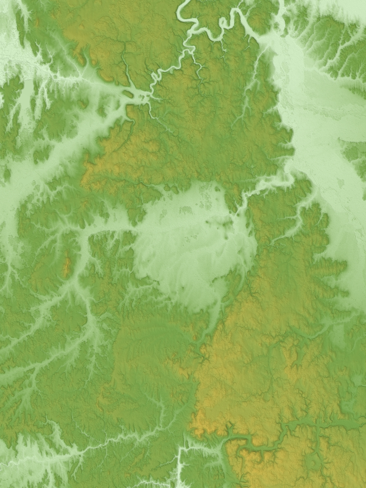
I first discovered the pattern while examining the Laramie Mountains in Wyoming. The pattern can make a crater, or a mountain, depending on polarity. I published two articles on these mountains last year. It wasn’t until this year I recognized that pattern I found was the same as Michael’s crooked smile.
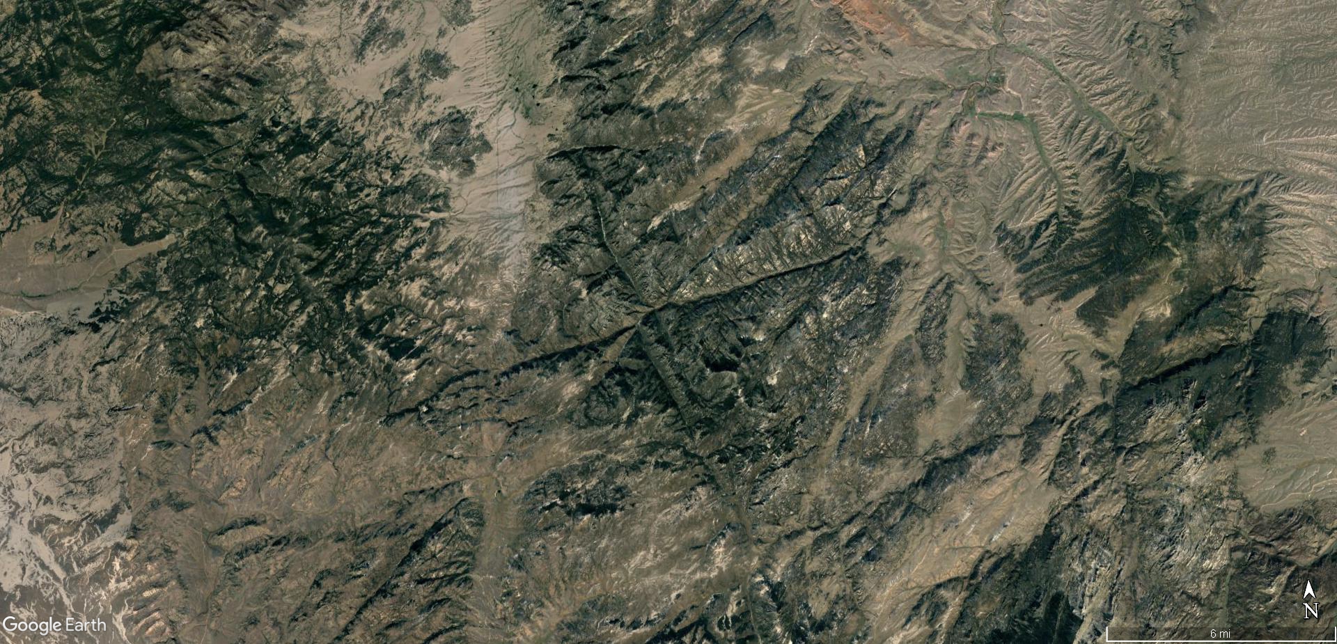
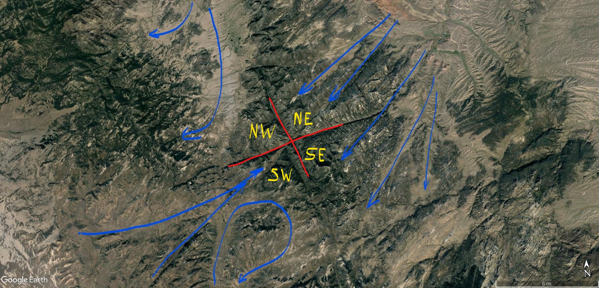
The Laramie pattern was caused by a plasma meso-cyclone – with it’s central updraft representing the real power discharge – or the firehose current – a positive ion current flowing up from the ground into the storm. The ground was negatively charged, and so, positive ionic matter from the winds collected there by static attraction, adhering to form the mountains. The mountains retain the shape of the winds that deposited them, which are in the Keystone pattern.
The pattern can be quantified and mapped with something called a phasor diagram.


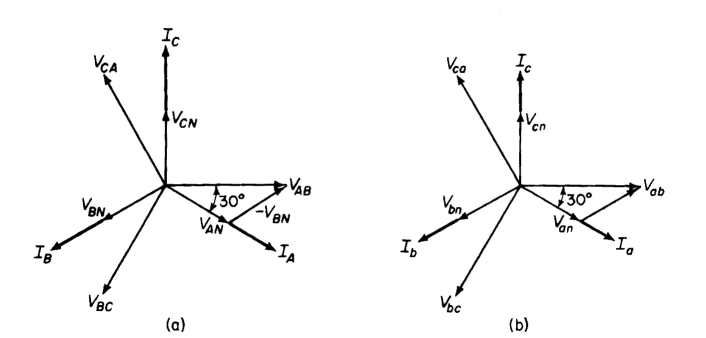
Phasors are 3-D graphs of vectors. For electrical circuits, they are used to determine the amplitude and direction of energy flow, or power at a given time. In alternating current, multi-phase systems, there are two or more waves out of phase with each other. Phasors are used to determine the resultant vector for the flow of power, voltage and current when there are multiple waves.
Manmade circuits work best when the energy sent ‘down the wires’ is aimed straight and doesn’t splash. Although some reactive power is needed, unwanted “splashing” is inefficient. It shows up as heat loss, signal noise and can even create plasma streamers from high voltage power connections.
We manage this with physical things like insulation, capacitors, transformers and generators to control frequency and amplitude and maximize what is called “real power”, or firehose power, as opposed to “reactive power”, or splashing.
Nature lets energy splash all over, and it results in plasma winds, storms and tornadoes. It also results in rock and mountain formation.
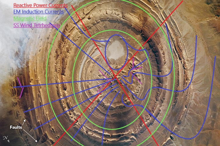
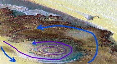
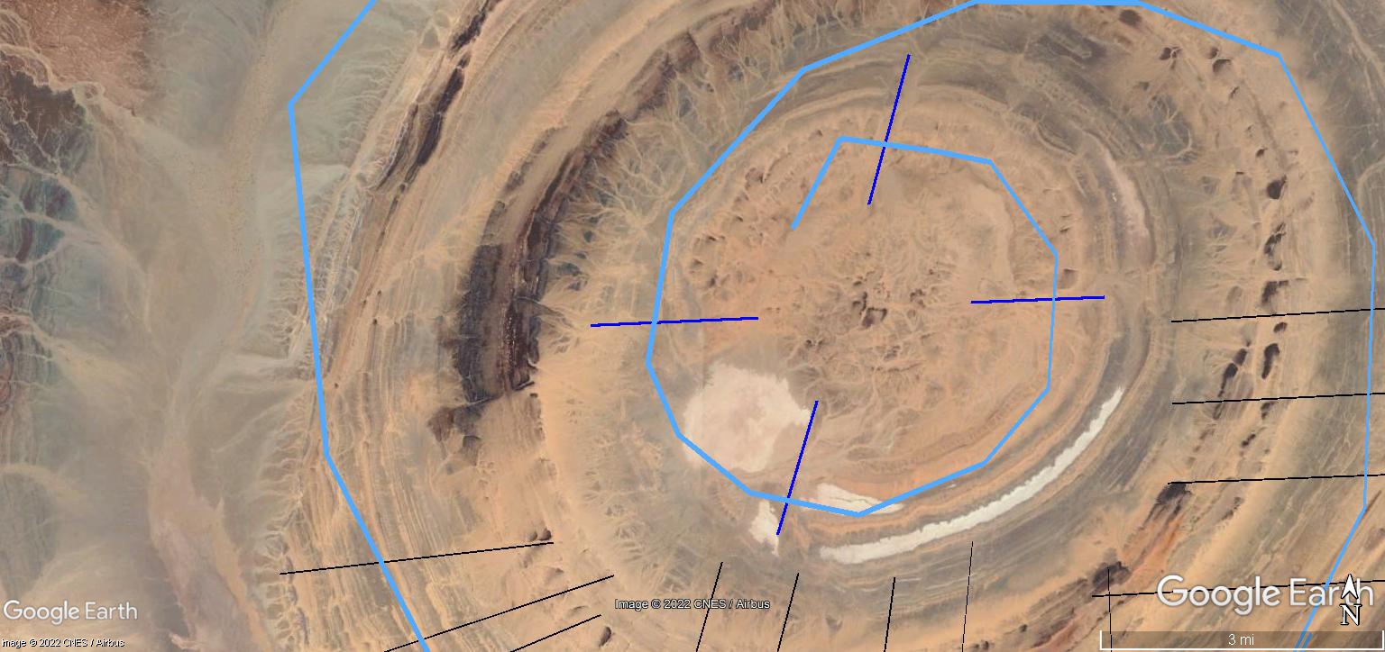
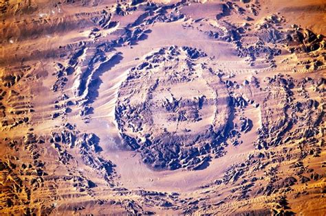
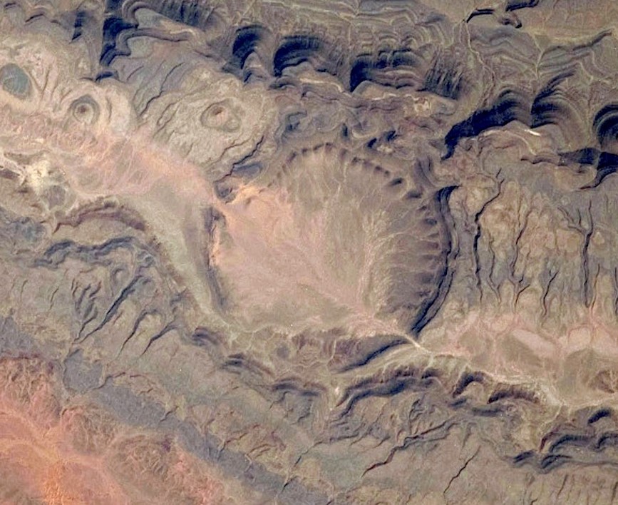
The next image you will recognize as the Richat Structure. The ‘compare’ image shows the basic Keystone pattern features. Wind direction is verified where possible by the triangular faces of tetrahedral hills formed in supersonic shock waves, and rock dikes (not marked on this image) caused by wind and shock wave.
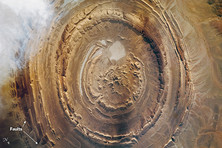
The Richat was created by a plasma tornado spinning like a buzz-saw between two opposing jet-streams. Tornadoes have a down-streaming, core wind inside the spinning updraft. A tornado is called a Marklund Current, and it has a central, core downdraft of ionic wind. That is why tornado genesis begins with a descending column of condensate meeting a rising swirl of dust. It’s a connection being made to complete a circuit of opposing positive and negative current flow.
The Keystone pattern, in the case of the Richat, was caused by induction winds that hugged the ground, being fed by the core downdraft, and blowing out beneath the up-drafting whirlwind.
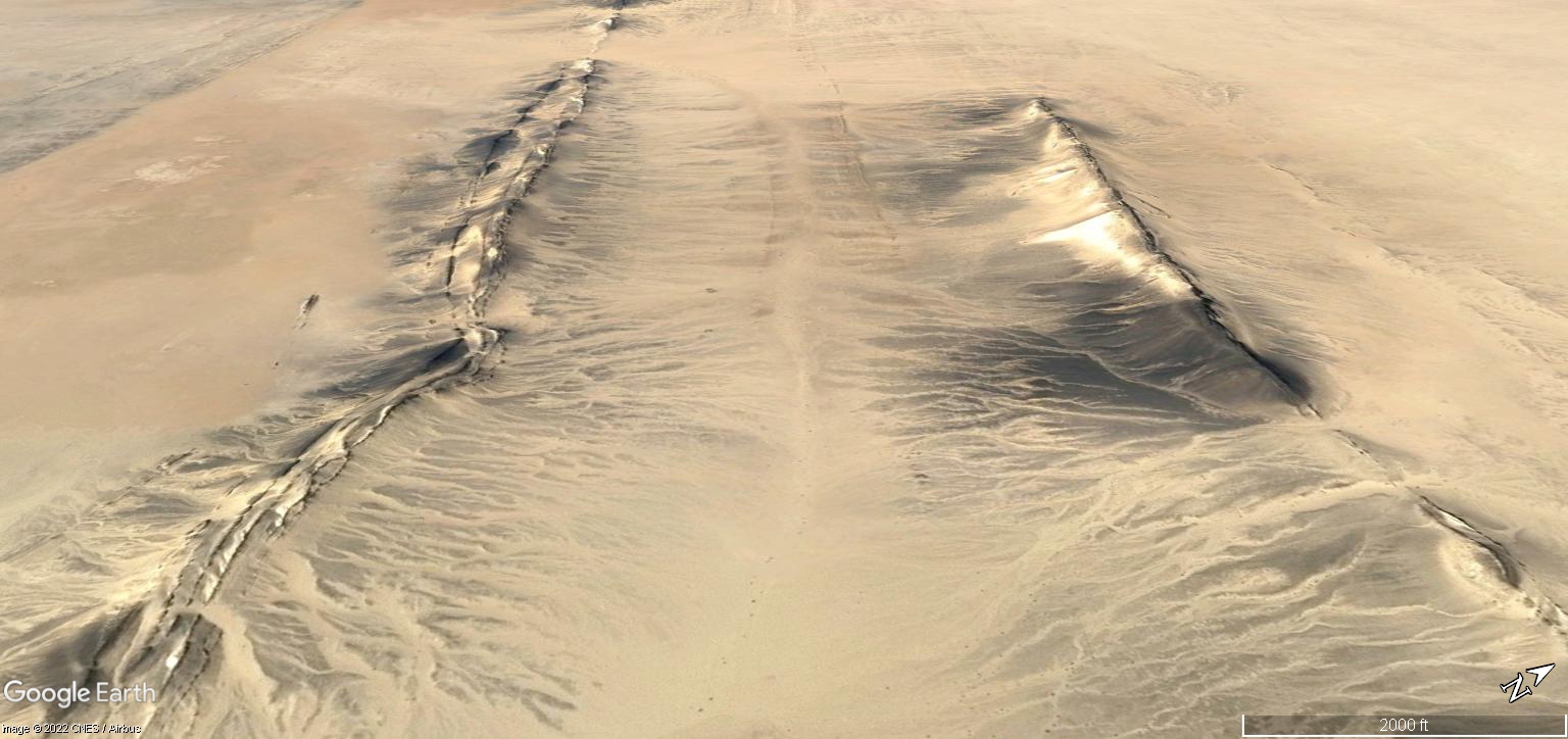
The next images shows the wind pattern of the whirlwind and the shock waves that resulted from the induction winds crossing under the whirlwinds. The winds cross orthogonally and leave cross-hatched shock features.


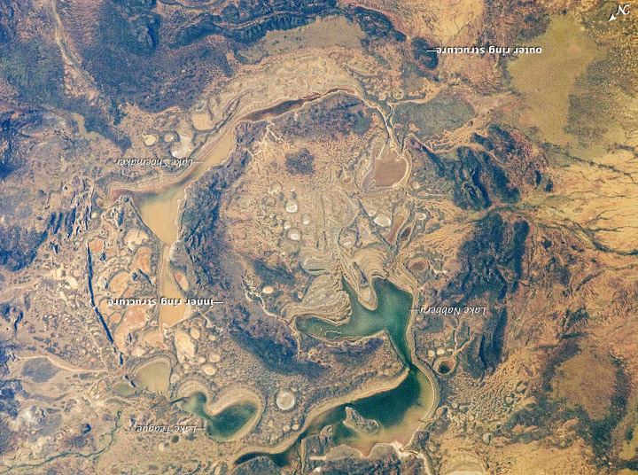
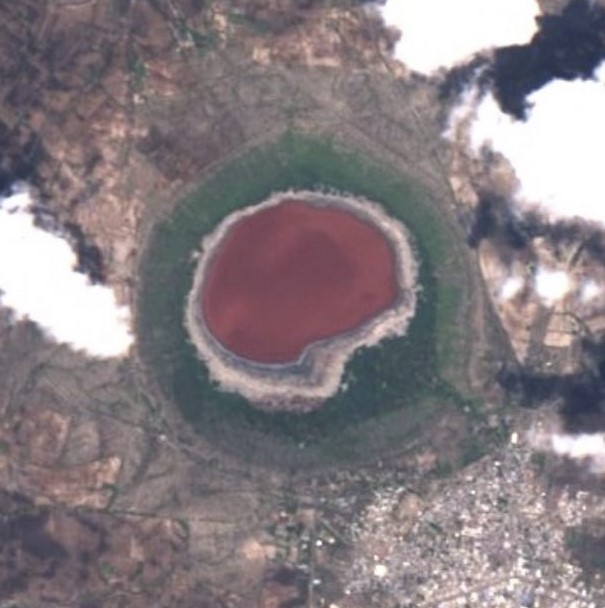
The Shoemaker crater in Australia provides another example of the Keystone. The crater doesn’t show signs of rotation on the ground, but the Red Cross of induced ground currents formed a rock dike that is fairly pronounced, as are wind patterned mountains at the Green Encircling ring of capacitance forming the crater rim.


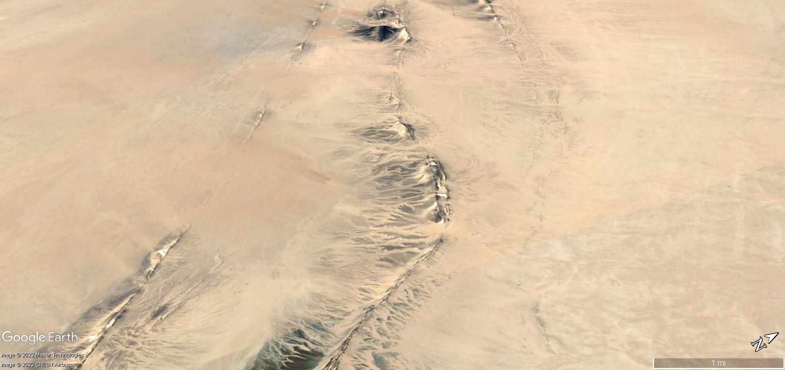
Induction features can be either anodic, or cathodic. If the ground is charged negative and a wind full of positive ionic matter blows over, a mountain of adhering matter will form. If the negative ground is exposed to a ground-to-ground discharge, it will sputter, or blast earth away and leave a depression. If the ground has positive matter in it, that will suck to the discharge and fuse to form a rock dike. Examples of rock dikes formed by ground currents are shown in the next images.


Anode and cathode features will appear alternately as current passes through the encircling rings of capacitance, making interference patterns in hills and crater rims.
If you are wondering, are these patterns on the Moon? They are not. Lunar craters are from Direct Current (DC) discharges, because the Moon is not alive with a geomagnetic field like Earth is. Earth is a multi-phased circuit, and these patterns result from multiphase Alternating Current (AC) interactions.

There are several craters that exhibit the fast unipolar winds crossing the crater rims caused by induction across the Blue Bar. Here are three in the next collage of images.
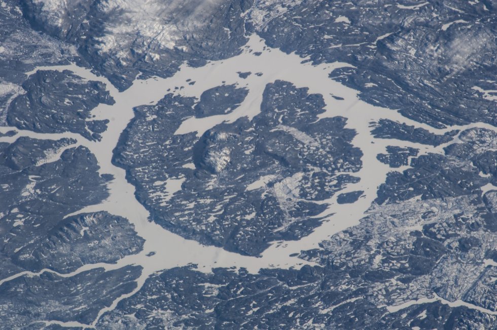
No one crater exhibits every feature perfectly. Some features are covered by sand, water, farms and cities. Some have eroded and some simply don’t develop in every condition. The patterns develop from reactive currents in both the air and ground. There is, however pattern consistency when several features are evident in the correct position with respect to the quadrants of the phasor. Here are several craters from around the Earth, most of them falsely attributed to meteors. They are the result of a discharge current flowing between Earth and sky. All exhibit aspects of the Keystone Pattern.

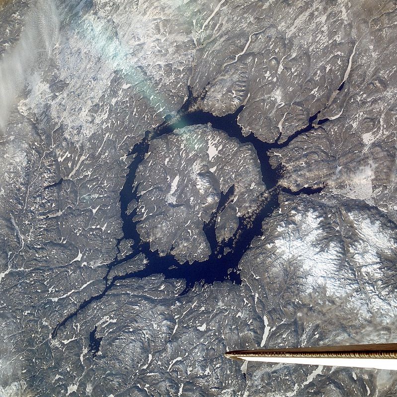


Note the “Q” in each ring. At roughly the five o’clock position, each crater exhibits a hooked shaped slash, or other anomaly through the ring. Of course, I’ve oriented the pictures so they are consistent, but note there is also similarity in the pattern of river channels connected to the ring to either side of the “Q” mark in most of the craters. So, there is a quick and dirty way to identify the Keystone pattern. Look for the “Q” with a lightning bolt through it.
Truth is always holistic… we’ve been trained to think our consciousness is constrained to the brain. It’s not.
Cheers,
