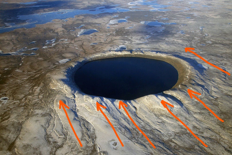
In Part 1 of Granite Cauldron, we discussed boulders and their formation. We looked at several examples where the granite displays unambiguous patterns that perfectly match the known behavior of hot, viscous fluids forming drops and flows at atmospheric pressure. We discussed my proposition that this is the result of a massive telluric current. That is, an electric current emerging from below Earth’s crust and diffusing into the crust, where it charged a conductive aquifer near the surface, causing electrolysis and generating heat that boiled the sand capping this aquifer.
To complete our understanding of the theory, and in particular why the ground boiled, it’s time to take a broader view of the mountains themselves to see how the cauldron came to be. It will help if you have also read, or watched previous articles on “The Keystone Pattern” , because that pattern is a definable, predictable consequence of current discharging into, or from the Earth, and will be referred to in this article.
Repeatable and predictable is as close as it gets to proof, right? We’ll look at how the Keystone Pattern is evident and then discuss the plausibility of electrolysis and heat making granite from sand.
The Cauldron
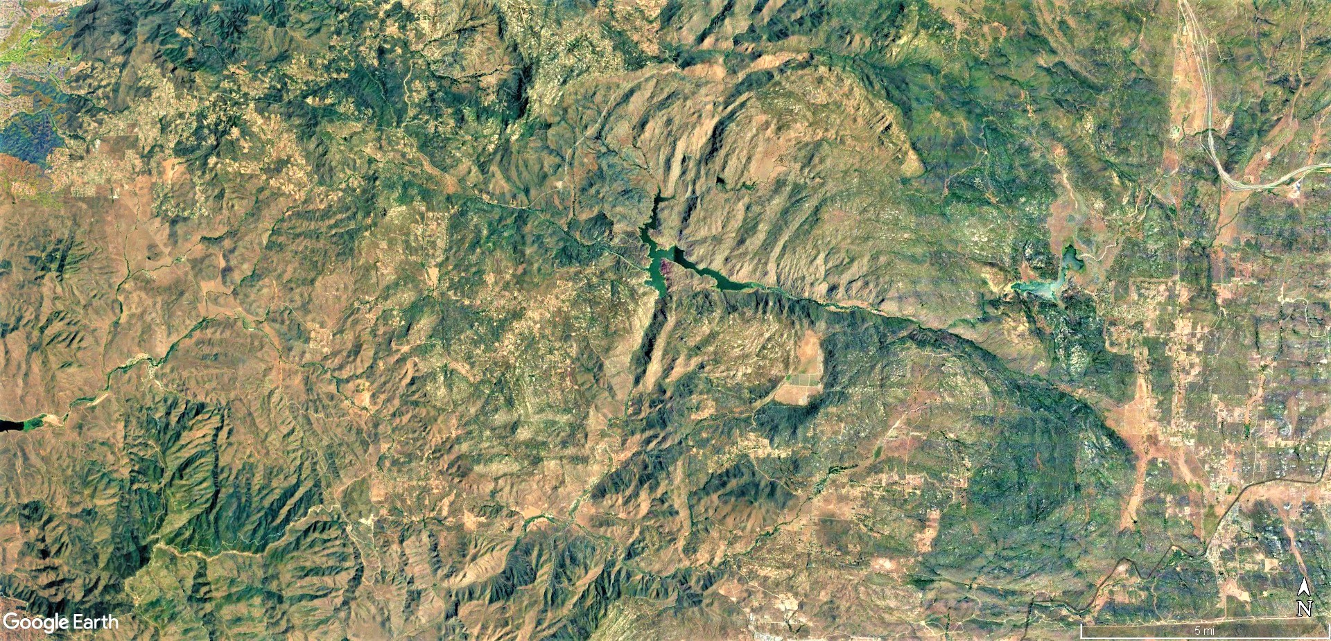
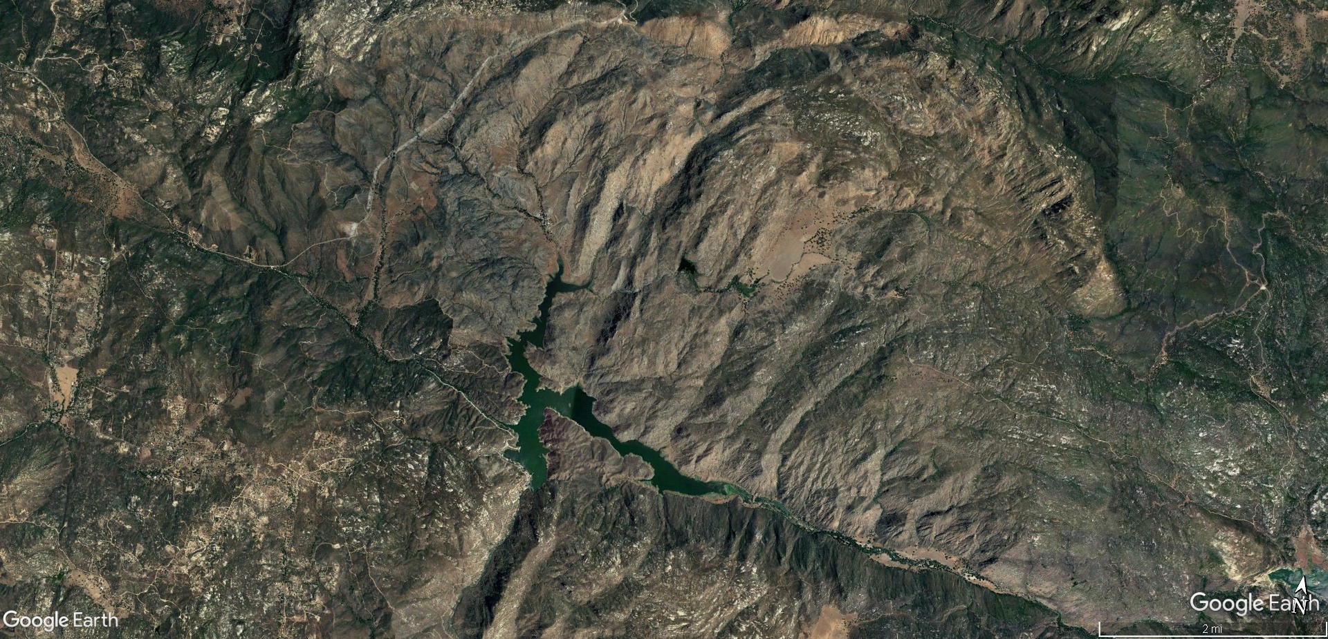
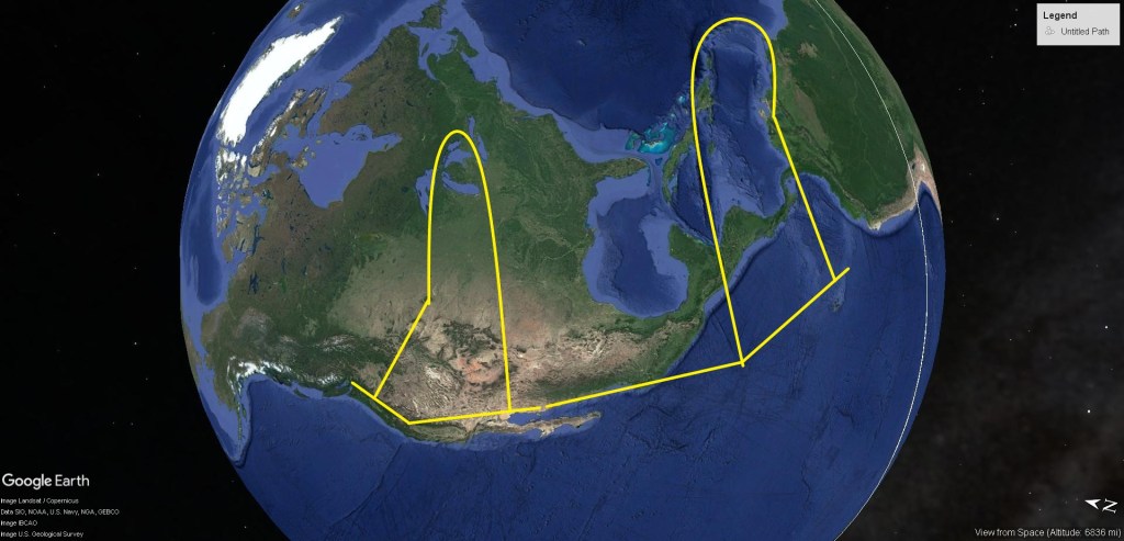
To orient yourself, look at the following Google Earth image, and use the slider to see annotations. The mountains in question are within the lower area circled. The city on the coast at the bottom of the image is Tijuana, Mexico, and above it, with the large bay, is San Diego.
The circles have crosses in the center, and you can see by using the slider, that these correspond to deep cut valleys, and the circles highlight valleys and highlands ringing the cross. You can also see several other circular, cross and parallel valleys elsewhere, but the features highlighted easily dominate the region.


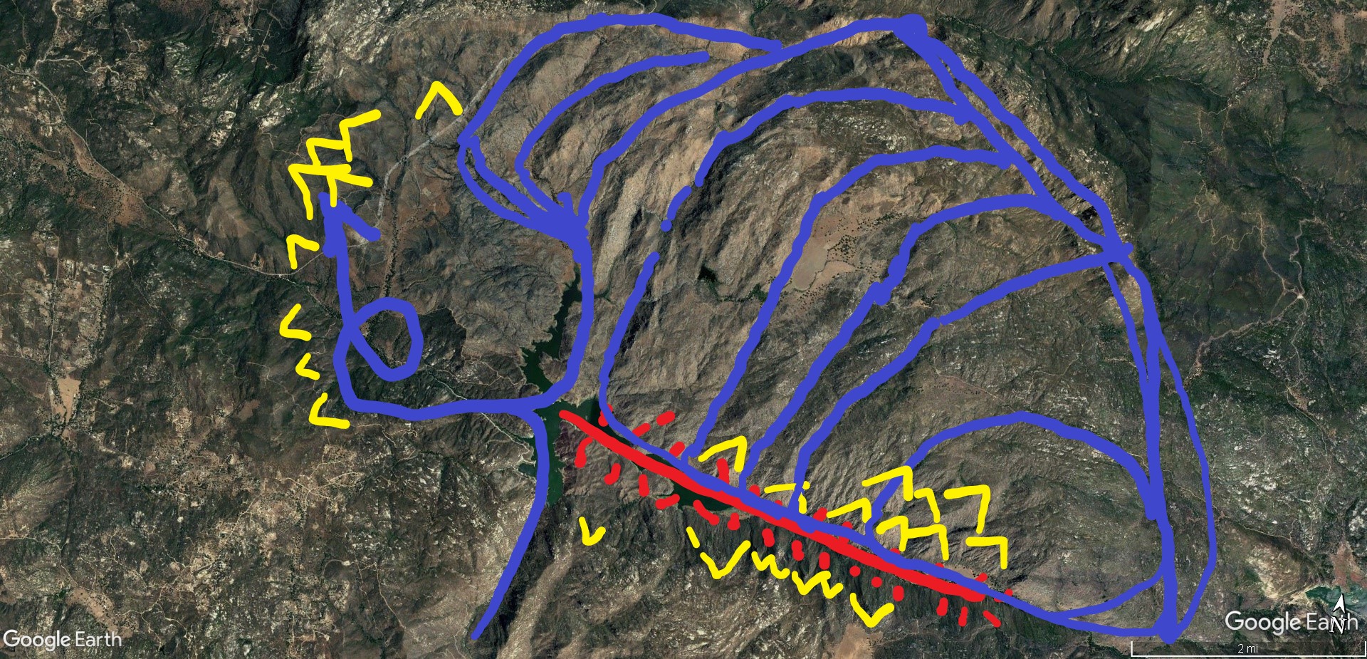
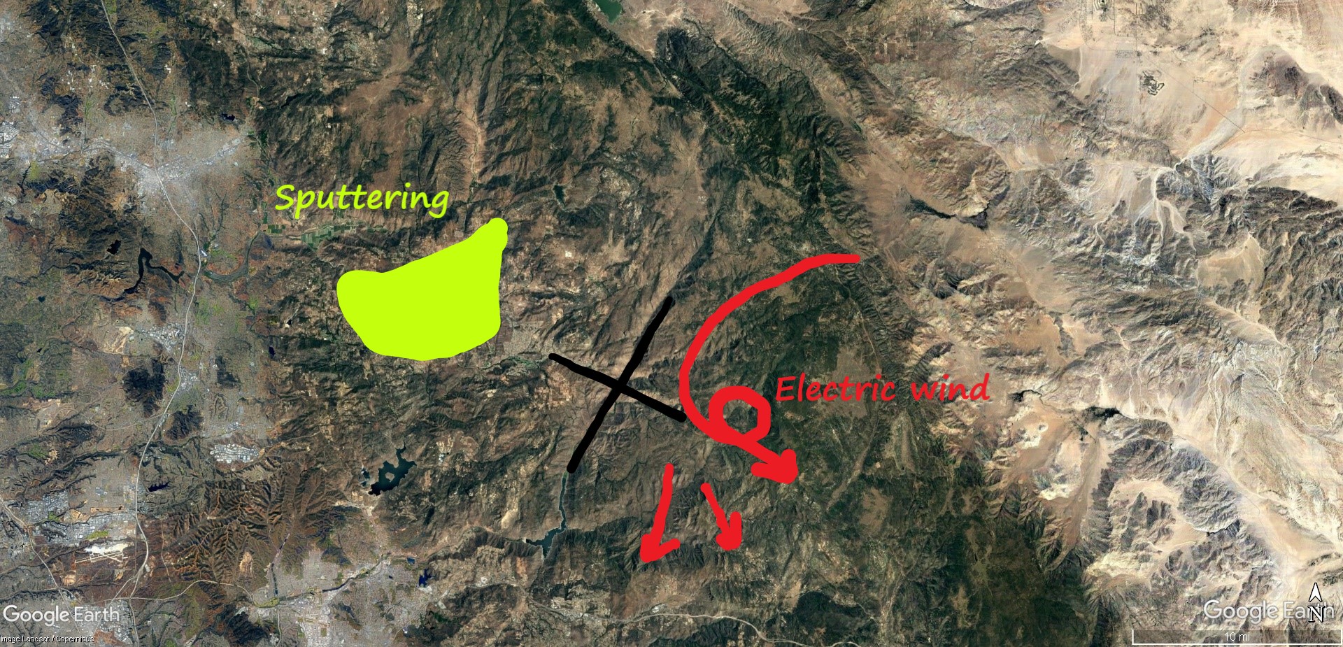
In the lower circle, in the lower-right quadrant below the cross, is Potrero where most of the photos in Part 1 were taken. A closer look at this area reveals more patterning to the canyons within and around the circle. The next image shows there are parallel, linear canyons in the upper right and part of the upper left quadrants formed by the “X”. Use the slider to see them highlighted in blue.
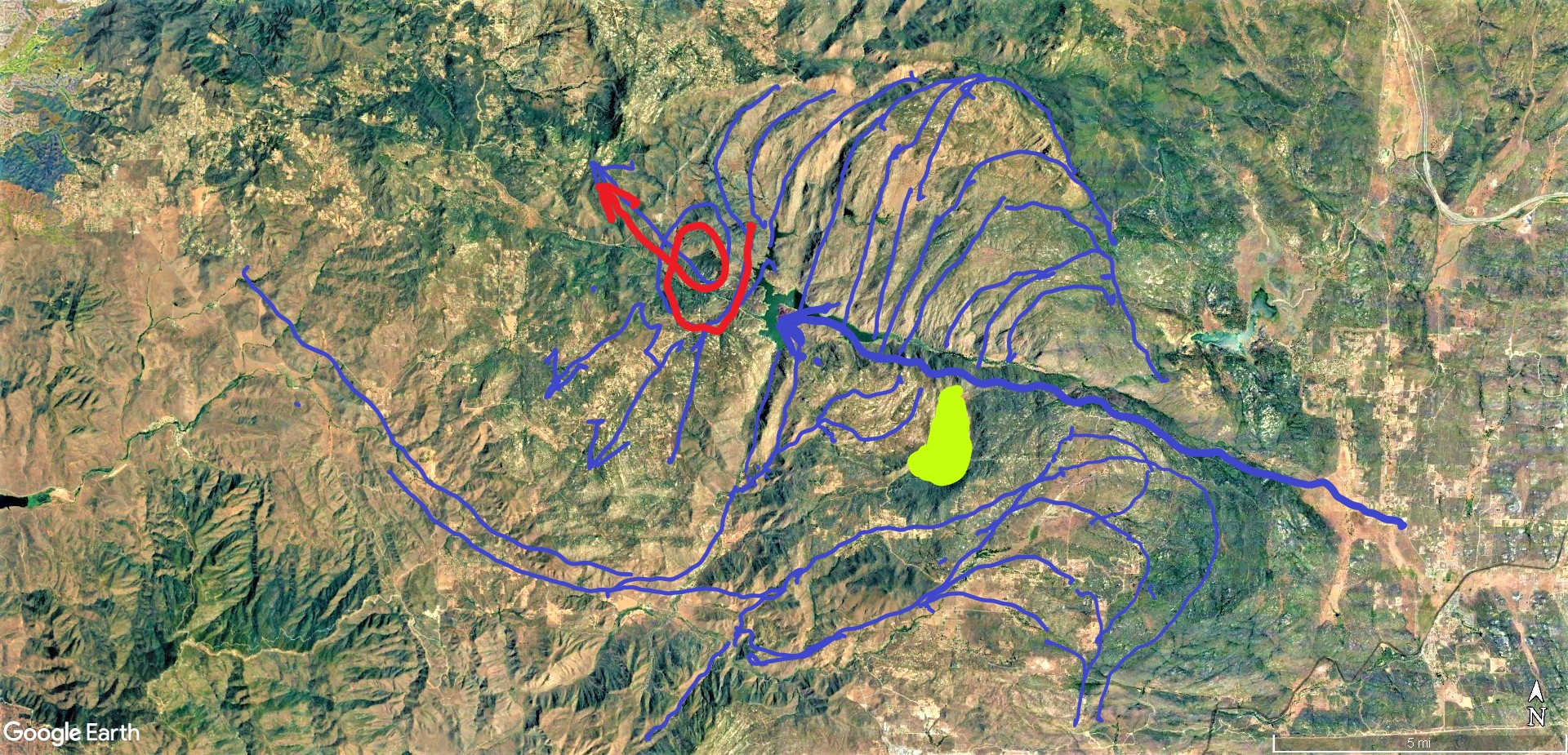
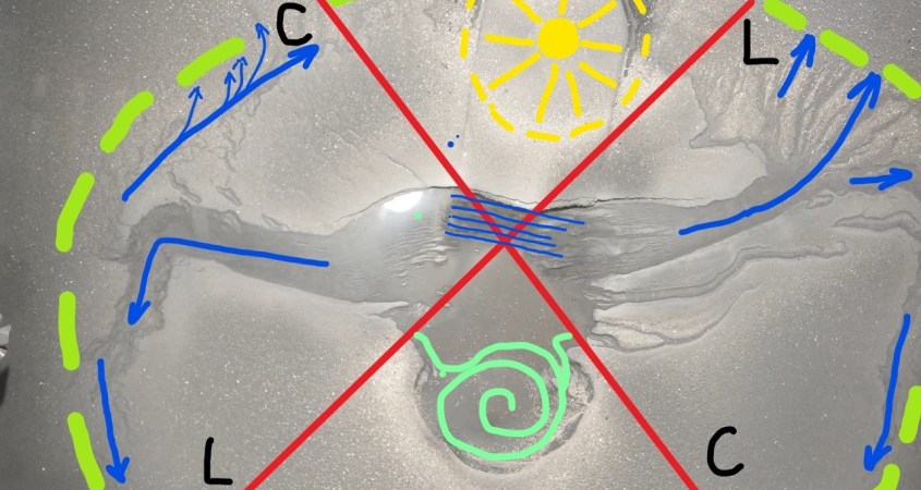
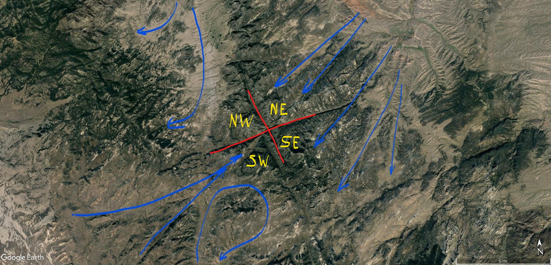
These canyons were cut by electric winds driven by reactive currents on the ground. Reactive currents are induction currents in the electromagnetic field surrounding a discharge. Reactive currents are at 90 degrees to the primary current discharging, so this is a pattern of currents and winds hugging the ground and flowing into, away from, and circling around the center of a discharge coming out of the Earth at the center of the “X”.
The annotation indicates in red where the winds twisted and lifted into a tornado along the left-hand of the cross, and opposite on the right is an area shaded green where electrical sputtering took place, leaving a large, flat bottomed valley. Both of these, and the linear winds are predicted by the Keystone Pattern.
As are the lower quadrant winds, which the canyons show blew radially away from the “X” in the left quadrant, and blew circumferentially around the “X ” in the right quadrant.

In the next annotated Google Earth image, the slider shows yellow and orange annotations where shock waves left tetrahedral patterns. The orange tetrahedrons were from supersonic winds exiting the tornado.
Tornadoes are a class of weak plasma discharge known as a Marklund current. It is, in fact, a coaxial circuit from cloud-to-ground with a positively charged current spiraling up on the outside, which is the dusty part of the tornado we see, and there is a central downdraft of negatively charged current. It’s this central downdraft that blows out from the bottom of the tornado at supersonic speed that caused standing-wave tetrahedrons to form in it’s blast zones in the left quadrants.
We don’t notice this outflow wind in the puny little tornadoes seen today, because a) nobody is looking for it, and b) it’s overwhelmed by the positively charged bulk of dusty wind being drawn into the rising outer rotation. But in the amped-up, high pot electric storm that made this tornado, the negative outflow was substantial and carved into the ground to slip beneath the spiraling positive inflow, and that is why it’s marks can be found on the landscape.
The yellow annotations are from shock waves caused by arc-blast from a ground hugging discharge that formed the cross, highlighted in red. This filament of arcing discharge heated and vaporized everything in it’s path, and the explosive wind of expanding gas left shockwave separation bubbles that formed these tetrahedrons.
Because the pattern indicates winds circulated counter-clockwise, the right hand rule says the current was coming out of the Earth. The winds followed the charge distribution on the ground, which was patterned by reactive currents. Reactive currents are currents induced by the electromagnetic field that surround the vertical discharge current. They are sometimes called eddy currents.
As the discharge circuit sparks the E-M field rotates, creating an interference pattern on the ground between magnetic induction and electric field induction, which are at 90 degrees to each other at the center of the discharge.
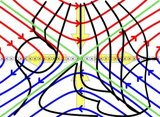
All of the features shown can be found in craters and mountains all over the planet, and some other planets, because it’s what electricity does. It’s a predictable, repeatable, fractal, naturally occurring proof that we live in an electric universe and, like us, gravity is just along for the ride. But more specific to the boulder cauldron, this pattern confirms that electrical charge welled from the Earth, with it’s charge concentrated at the center of the “X”.
“X” marks the spot. The magnetic field forms the ring around it. But magnetism takes time to develop, so is out-of-phase with the electric field allowing hysteresis into the circuit, and standing waves result. Each quadrant exhibits a particular shape of charge distribution as the E-M field modulates, as leading and lagging induction currents form and the dominating force shifts from the magnetic to electric field.
This pattern is just an interference pattern like the bars of light produced in the famous “two slit” experiment. It is more complex, because it involves multiphase, alternating electric current and magnetic fields which are things that have stumped consensus science for the past century. This pattern should be well understood and well recognized, but it’s not, even by electrical engineers because they don’t dive deep into understanding the flow of energy and ignore the obvious influence of the ether. They use convenient approximations, graphs and models and ignore fidelity in the fundamental waveforms.
The ground-sky interface presents a huge wall of resistance. Current welling from the ground suddenly loses its conductor – all the water and metals in the ground – and meets the high dielectric air. Even if the air was a conductive, dusty plasma, as it most certainly was, the change in density from solid-state to gas presents a huge step resistance. Resonant frequency discharge occurs when back-emf forms, reflecting off this resistive barrier and superpositions – matches frequency – resonates, in other words, like a shock-wave and forces the energy orthogonally from the vertical plane to the horizontal, across the face of the earth, gouging channels in its path due to the fact the energy wants to stay in the ground where it finds conductance, and because it’s arc-blast is an explosive wind.
To better understand the patterning it helps to see the vertical channeling that occurs in coronal discharge currents. Dark-mode, drift, or coronal currents are used in manufacturing to electrically apply coatings; a process called sputtering, or to remove material; a process called electro-dynamic machining, EDM. In both processes there are two electrodes: one giving-up material and one gaining material – a cathode and an anode, – and a circuit through the atmosphere between.

Such currents pattern themselves into circuits of two-way, positive and negative channels. These channels are what appear at opposite sides of the “X”, where sputtering occurred on one side and a Marklund current on the other. Positive and negative biased plasma channels precisely as experiment produces in point-to-plane coronal discharge, as shown in the diagram: “Primary Reaction Channels in Coronal Discharge”.

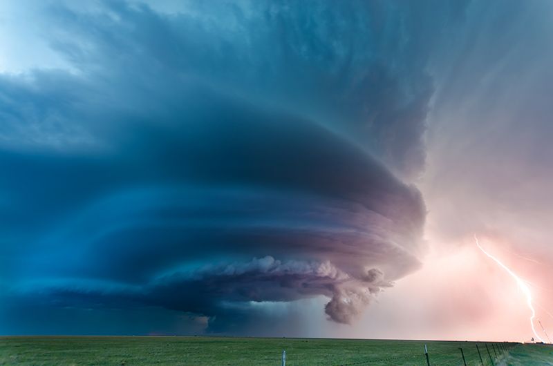
When these mountains were built, the electrodes were the Earth’s crust – ground – and plasma charge concentrations in the clouds – storm. This formed an electric field geometrically similar to a classic point-to-plane discharge in air. The footprint of a tornadic wind and sputtering, juxta positioned precisely as experiment predicts, is worth noting. It’s the same damn pattern as a meso-cyclonic thunderstorm, with it’s rain curtain, down-burst channels, updrafts and Marklund currents located in the same damn places, every damn time. When will these so-called scientists notice?
The sputtering channel and the Marklund, or “electric wind” channel are one and the same channel looping through the electrode. It is a coronal loop, which is the same electrical circuit that makes coronal loops on the Sun. It’s the same electrical circuit that drives thunderstorms and the storms on Jupiter. It is the same electrical circuit witnessed and recorded by ancient people – probably just before it killed them.


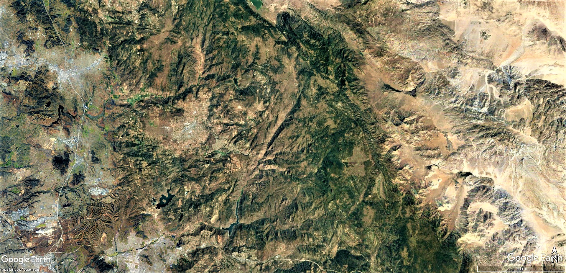
To demonstrate how this is a predicable, repeatable, fractal expression of a coronal discharge, look at the other, larger region circled in the first image at the beginning of the article. Below both circled regions are compared, and I have highlighted where the electric wind and sputtering channels left their marks. They are mirror images of each other. The quadrants are simply rotated opposite each other. Both have counter-clockwise rotation.
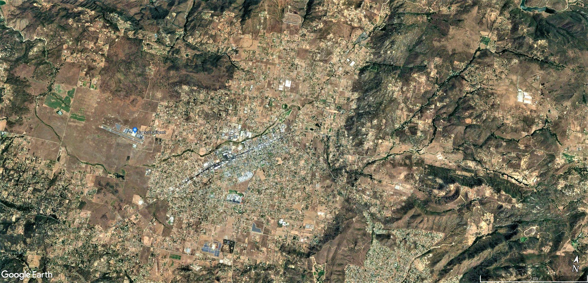
Looking closer, one can identify the sputtered region is now occupied by the City of Ramona. Typical of sputtering, it leaves a flat-bottomed, kidney-shaped valley ideal for farming, grazing and occupation.

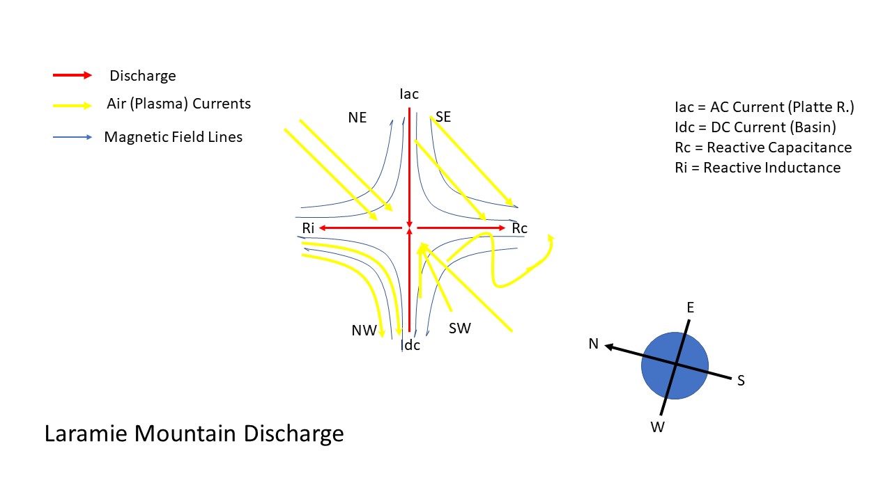
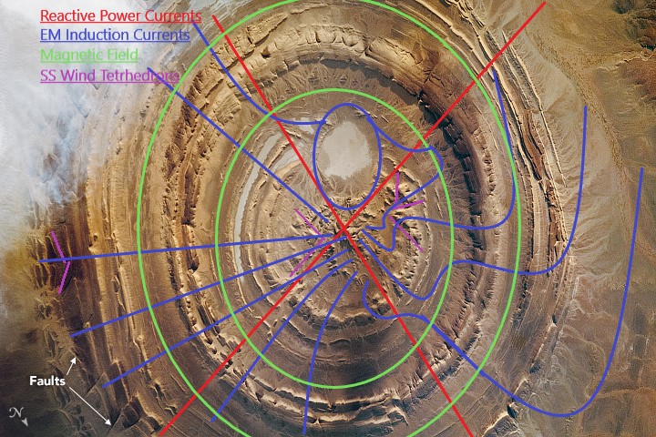
The Keystone pattern is a set of patterns created by a primary discharge current and it’s reactive currents in an E-M field, and will display at an interface where coronal discharge occurs due to a step rise in resistivity, like on a capacitor plate, or the surface of an atmospheric planet. Like fingerprints, or snowflakes, they are of a pattern set, but no two are identical, because of local influences like the materials involved, which are never precisely the same. A similar pattern was previously shown to form the Laramie Mountains in Wyoming and the Richat structure in Mauritania.
The blisters begin on the Baja Peninsula, and continue up the coast, eventually to become the much more energetic strato-volcanoes of the Pacific Northwest. These southern blisters are still-born volcanoes, whose energy was expressed in chemical outpouring from electrolysis, rather than the explosive convulsion of a sub-surface arc discharge. Even today, the region is hot and boiling, with several hot springs and even utility-scale, geothermal power production in the desert valley to the east.
The volcanic lineament all along the North American plate boundary, and other continental plate boundaries as well, is caused by electric current that runs the edge of the boundary as it drifts from beneath the plate. The continental plates are thick cratons of basalt piled with layers of sediment, and makes a collector plate to current welling from the Earth.
We can deduce this has to happen, because Earth is inducting electric current from the Sun at the poles and Earth doesn’t store it all. We know the crust forms a spherical capacitor in the path of this energy, and the patterned charge distributions that result from capacitance can be seen both in it’s geology and in it’s weather. The Keystone Pattern is one of several examples of tested, or testable phenomena caused by electromagnetism. Shock wave tetrahedrons are another. Tornadoes, cyclones and meso-cyclones are another. The alternating El Nino/ La Nina currents that influence the climate of the entire planet is another. These are all patterns of motion, phase and frequency provably caused by the planet’s own electromagnetism. We can also measure it, in the form of telluric currents and potentials, if we want to look.
The continents present extra layers of capacitance, which means they collect charge. That charge then leaks around the edges and self-organizes in a patterned E-M field, called the fringing field. Current flows in the fringing field, heating things up and wreaking havoc, like earthquakes and volcanoes.
The reason this region boiled and electrolyzed instead of bursting in volcanoes is due to the geometry of the Telluric currents in the fringing field. This has also been discussed before, in “Subsurface Birkeland Currents”. Fringing currents not only occur at the continental edges, but also criss-cross continents along old plate boundaries of the earliest cratons. This forms intersections in the current, called triple junctions, and creates cyclic current loops. There is also feedback input from electric storms, solar storms and cosmic wind. The net effect is the fringing currents are self-organizing circuits with functionality. A circuit of triple-junctions and ring currents with amplifying inputs is the description of an Operating Amplifier.
Op Amps switch current flows, directing current at each junction by amplifying, or resisting it. This region lies between junctions, in the “bridge” of the Op Amp, where the current was held to a lower level by the geometry of the circuit itself.
One triple junction is immediately south of the blisters we’ve been discussing, and can be identified by the Pinacate volcanic field in Sonora Mexico. Another is to the north near Mendocino, California.
Between these nodes the number of volcanoes is greatly reduced and are distanced apart compared to the continuous line of huge strato-volcanoes to the north of the Menodicino node. Likewise the profusion of volcanoes south of Baja node continues through and beyond Mexico. Between there is the Shasta, Lassen and Mammoth volcanoes and a few lesser eruptions, but not with the energy and density elsewhere on the lineament. Not coincidentally, this is also the exact same reach parallel to the San Andreas fault, because the fault is from a discharge inducted between these nodes.


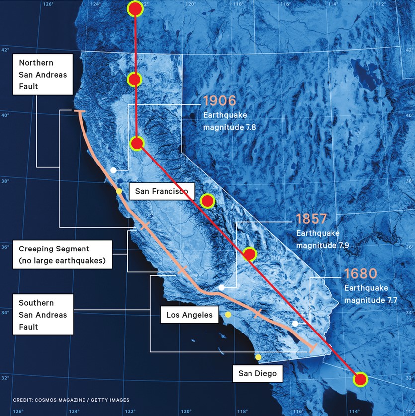
It all makes perfect sense looked at as an Op Amp circuit. The fault parallels the continental fringing field current. It’s at a shallower depth and came after the mountains were built, so came after the fringing field current. It connects between triple junctions in the bridge of the Op Amp, where current can bypass around the ring portion of the circuit. It creates a high voltage/low current situation between the nodes that induced a parallel current. This is sometimes called stray capacitance, because the induced filament is field aligned to the bridge current and it acts like two, thin linear plates of a capacitor. The induced filament sparked, creating the fault and still causes occasional earthquakes.
The entire Pacific coast and it’s features such as the San Andreas fault, the Sierra Mountains, San Juaquin Valley, the coastal ranges including the subject mountains, and even the Great Lakes on the other side of the continent can be explained in great detail by the electric circuits in the fringing field. But that takes us beyond the scope of Inkopah’s rocks.
The Rock
In case you think the idea granites are produced by electrolysis is crazy, please look into how elemental silicon was first produced. In 1854, pure elemental silicon was first produced in crystalline form as a product of electrolysis.
Sudden charge diffusion into a salt water aquifer beneath, or within layers of sand, perhaps still saturated having been dredged from the sea by tsunami, would evolve blossoms of oxygen by electrolysis that channel to the surface. Hydrogen would evolve, too. But being the smallest, slipperiest molecule, hydrogen would escape first, easily permeating through the porous sandstone overburden,. What hydrogen didn’t escape would cling to the sand giving it a positive charge.
The oxygen would follow, forming an ionic flow of current which would heat-up the channel. Electrolysis itself does not generate heat, but the current of ions, free electrons and chemical reactions would. It would boil and superheat the water, perhaps bringing it to triple point, where electrolysis more freely takes place. Oxygen would react with ions in the sand, especially iron. There is every evidence of this, as the rock and ground are suffused with iron pyrite, mica and the orange stain of iron rust. Everything was very hot, but not subject to the explosive thermal shock of arc discharge that vaporizes matter.
Granite, like 95% of all rock on the planet, is composed of silicon and oxygen in the form of silicates, like quartz. Almost all rocks are essentially silicon, oxygen and a small percent of other elements.
Oxidation is a reaction, whereby oxygen, in this case, gives up electrons to become a cation, and another element gains the electrons to become an anion. When iron rusts, the iron is oxidizing because the iron is stealing electrons to become iron oxide. Any metal, except gold, will oxidize.
Silicon is particularly wont to oxidize with oxygen to create rocks. Granite in particular is a conglomeration of the micas, clays, quartz and feldspars listed below.
| Major group | Structure | Chemical formula | Example |
|---|---|---|---|
| Nesosilicates | isolated silicon tetrahedra | [SiO4]4− | olivine, garnet, zircon… |
| Sorosilicates | double tetrahedra | [Si2O7]6− | epidote, melilite group |
| Cyclosilicates | rings | [SinO3n]2n− | beryl group, tourmaline group |
| Inosilicates | single chain | [SinO3n]2n− | pyroxene group |
| Inosilicates | double chain | [Si4nO11n]6n− | amphibole group |
| Phyllosilicates | sheets | [Si2nO5n]2n− | micas and clays |
| Tectosilicates | 3D framework | [AlxSiyO(2x+2y)]x− | quartz, feldspars, zeolites |
They are all crystalline compounds of electrically bound silicon and oxygen.
Silicon melts at 2577 degrees F, 1414 C and boils at 5909 degrees F, 3265 C. However, it’s unlikely temperatures this high were reached.
Application of an electric field with both AC and DC current has been tried and proven to lower the melting temperature of silica substantially, even to only a few hundred degrees – temperatures one can achieve in a conventional oven. Therefore, if electrolysis occurred, the electric fields generated would have naturally lowered the melting temperature by helping disassociate the crystalline bonds and liquify it. The presence of water also lowers the melting/boiling point of silica.
Electrolysis is accelerated by heat, saltwater, and capillary action – all present. The reaction is especially helped if the water is supercritical. That could be the case for water welling up from the deep under significant pressure at a temperature that melts sand.
The piezo-electric effect of current in the rock crystal itself would have had an effect, too, amplifying the release of free electrons and literally vibrating the rock. Electrically, granite is an excellent conductor, a chemical sink for oxygen, and, under stress, a piezo-electric generator.


Essentially all the conditions to promote boiling and electrolysis are present, from the materials to the energy welling from deep in the Earth.
To show how easily granite conducts electricity, the following film produced by James Hammond shows coronal discharge across an air gap between a granite block and electrodes. Notice that current diffuses entirely through the granite,, expanding to reach the entire electrode on the bottom. Also note, these discharge filaments are little plasma tornadoes. This may give you some visual clue to what the granite cauldron once looked like.
Video courtesy of DiveFlyFish.
After some time, the coronal discharge begins to eat away the rock, forming conductive channels that starves current from the other filaments and focuses it ultimately into an arc-mode discharge. Jim’s experiment is reversing the process of granite creation by disassociating crystalline bonds and melting and dissolving the rock.
Only electricity can do that – both construct and destruct matter. Interference is always either constructive, or destructive. Which brings up the bigger question: What is your interference pattern – what energy do you project?
We live in a fractal universe of energy and information, holographically presented us from without and within. Look inside to find the universe, because every element of a hologram contains the entire image. Every element of our being holds the answer, if we let the signal through. And, our energy projects tomorrows pattern. The future is in our hands.
So let’s make it better.
Cheers, and best of luck.

The actual temperatures were so low that the rock could be deformed by hand. There are hand impressions and footprints in rock in some places.
LikeLike
Awesome work mate! Would love to see your current diagram for the Devil’s Marbles, Northern Territory, another prominent bubbly granite outcrop in the middle of a truly cataclysmic mountain range (here: https://www.google.com.au/maps/@-20.5653019,134.265688,2269m/data=!3m1!1e3?entry=ttu). And as I posted on Part 1, the ancestors of the aboriginal locals saw the catastrophe in real time and their eyewitness mythological account survives to this day.
LikeLike
What is their account?
Do they describe the rainbow snake at all?
LikeLike
Why did you not ‘like’ the article?
LikeLike